| ST165 | ST185 | ST185RC | ST205 | Maintenance Item |
|---|---|---|---|---|
| X | X | X | X | Throttle Position Sensor (TPS) Adjustment |
| X | X | X | X | Replacing the Rear Differential Cusion |
| X | X | X | X | Servicing the Rear Differential |
| X | X | X | Solving Code 54 | |
| X | X | X | Solving Code 54 For Continuous Intercooler Operation | |
| X | X | X | Servicing the Intercooler Pump | |
| X | X | X | X | Knock Sensor Replacement |
| X | X | X | X | Adjust Clutch Pedal |
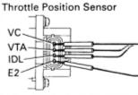
Here are the Toyota OEM specs for checking and adjusting (if required) the throttle position sensor on the ST165 and ST185/ST185RC. Use a feeler gauge as directed to measure clearance between throttle lever and throttle stop screw, and measure the current across the indicated TPS terminals. Ā
| Clearance | Terminals | Resistance (ohms) | ||
|---|---|---|---|---|
| ST165 | ST185/ST185RC | ST205 | ||
| Nil | VTA - E2 | 0.2 - 0.8 | 0.47 - 6.1 | 0.3-0.8 |
| 0.50mm (0.0197 inch) | IDL - E2 | Less than 2.3V | 2.3V or less | 2.3V or less |
| 0.70mm (0.0276 inch) | IDL - E2 | no continuity | no continuity | no continuity |
| Throttle fully open | VTA - E2 | 3.3V - 10.3V | 3.1V - 12.1V | 3.2V - 4.9V |
| Throttle fully open | Vc - E2 | 3V - 8.3V | 3.9V - 9V | 4.5V - 5.5V |
If adjustment is necessary, then the following procedure applies to both models:
Terminals are as follows (viewed standing at front of car), ST165, ST185 and ST205 are the same:
PLEASE NOTE. I AM NOT A LICENSED MECHANIC. THESE INSTRUCTIONS ARE FOR REFERENCE ONLY AND I DO NOT TAKE RESPONSIBILITY FOR ANY DAMAGE DONE TO PROPERTY OR BODY AS A RESULT OF THEIR USE.
I used a 1991 Toyota Celica shop manual as a reference and the torque values given are from this manual. The instructions are in order of disassembly with bolt torques given for re-assembly. All the listed steps are necessary. I wouldn't list them if it wold have worked otherwise.
With thanks to Nathan
Servicing the diff itself is easy. The Toyota repair manual, or the Chiltons has a very good description of the procedure, so I don't expect that your mechanic will not be able to handle this.
The transfer case is a collection of worm gears i.e. six or eight (I forget) smaller helical gears arranged around a large central helical gear fixed in a cylindrical case. The central helical gear is actually two identical gears arranged end to end with a spacer, and a pin bearing in between. At the two ends of this larger helical gear assembly are two small clutch-like disks i.e. basically shock absorbers. When the freeplay between these two larger helical gears increases, your drive shafts will tend to move outwards before engaging.
Look at diagram below :
                                        Pin
Clutch  |  Worm Gear  |  Bearing  |  Spacer  |  Worm Gear  | Clutch

        (((   \\\\\\\\\\\\\\\\\\\\\\\\\     ||||||||||
||||||||||||||||||||||||  /////////////////////////  )))
        (((   \\\\\\\\\\\\\\\\\\\\\\\\\     ||||||||||
||||||||||||||||||||||||  /////////////////////////  )))
        (((   \\\\\\\\\\\\\\\\\\\\\\\\\     ||||||||||
||||||||||||||||||||||||  /////////////////////////  )))
        (((   \\\\\\\\\\\\\\\\\\\\\\\\\     ||||||||||
||||||||||||||||||||||||  /////////////////////////  )))
(Sorry for the quality of the diagram)
You can solve this problem by simply :
After you've eliminated the freeplay in the large helical gear, re-install the ring of smaller helical gears. Some of them may be a little loose due to normal wear and tear. I swapped mine around until I found a configuration that didn't have any freeplay. Also, after you put the diff back together, don't be surprised that you may have difficulty turning the ends a little. Eliminating the freeplay makes everything rather tight. Also, you may find your right and left wheel appear to be locked together i.e. turn one wheel, and the other will move in the same direction. Don't worry, as the diff will have to be run in a little first before things unlock themself. Remember to take it easy the first 200 miles or so.
Once I understood how the diff. worked, rebuilding it was really very simple. Also helps if you have a spare, like I did, compliments of the local scrap yard...heh heh!
There are numerous replacements which will work i.e. TRD, Cuzco are direct replacements, and will cost you around USD 1,000 from Japan. My research indicated that Quaiffe makes one that may fit. You may also like to try contacting Kazz.
IMHO the Toyota unit is a tough little bugger, and takes a lot of punishment...quietly. All drop-in race replacements are a little noisy. Don't know about the Quaiffe, but it should be fairly comfortable. Nonetheless, at these prices, it's worth trying a rebuild first.
Thanks to Chris Chin for the above information
I do ALL work on my car, but an Error 54 code was stumping me - I considered taking the car to a Main Dealer,
but, then I thought how likely is it that they are familiar with a system on an old car that had a relatively short run?
So I gave it one more bash. If you have this problem it will probably stress you out as much as me -
especially the huge amount of power you loose by the ECU limiting the boost!!
My problem was the pump didn't appear to come on and I could find little information about the system.
After driving the car the intercooler on top of the engine was very hot (as hot as the engine!)
Here is what I found, it is not exhaustive and I never came across any wiring diagrams so some is guess work.
The pump is under the battery - the pump connector had two power connections and 3 others which I assume are
to sense the motor is turning. I measured continuity across the motor which stayed the same when I turned it -
so I suspected the motor was OK (Plan a couple of hours to remove that - don't do it first like I did!!!!).
I also removed the intercooler level switch and tested it with a meter.
I couldn't find an intercooler computer like on the ST165 so I assume the control for the intercooler is in the ECU now -
powering the Intercooler Relay mounted on the Radiator.
The relay is powered by the 30AMP CDS relay in the fuse box near the battery.
Once I had changed the blown fuse and suspected all was OK I still kept getting error 54. This was because the water level had gone down because of the pump starting. I topped up and the error continued. I discovered that you have to top up the intercooler and replace the cap while the intercooler motor is running as it drags the water level down an inch or two.
To make the intercooler run permanently while doing this you can either remove the relay and short the two
pins to the front of the car (I'd be reluctant to do this because if you do it wrong you COULD BLOW the ECU).
How I did this was to carefully remove the cover off the relay. Turn the ignition ON, but, didn't start the
car and pressed the relay contacts at the front. You should hear the pump run and air gurgle through the system.
The level will drop down - fill the system to the top - put the cap back - and release the relay.
The antifreeze should be 50/50.
There were two satisfying aspects to this - 1. When you tear down the motorway stop and put your hand on
the intercooler it is stone cold. 2. You wouldn't believe the difference it makes to driving the car once the
boost pressure is back to normal.
Sorry this is a bit low on precise detail - but, it will give you an idea of the system for troubleshooting.
Finally, Another problem I had when I got the car was I couldn't find the oil filter - everybody said it
should be on the front near the Alternator - well it is actually underneath the car to the front of the sump
in line with the drain - This is great because when you remove it you don't get oil down the engine.
I am slightly worried that the filter could get smashed on the ground though.
Thanks to Keith Fisher for the above information
Well it's done...I finally hacked the stubborness of the GRP A, CS, RC ECU!!! The mod is a permanent one i did using 2 ceramic resistors to fool the ECU into thinking the water pump for the intercooler is still connected. The globe worked great, BUT a globe can blow out, and you will get a fault code in your ECU again. For anyone who wants to do this mod the specs are as follows for the resistors you will need.
Ceramic wirewound resistors - 17w 15r (not sure what the 15r stands for) avaliable from RS Components PN : 206-1647 @ $8.60 for a pack of 5. Any electronics part supplier should carry these resistors in stock.
To install, you must find the intercooler pump, then follow the wires up towards the battery (makes the job a lot easier to remove the battery) and behind the headlight. Find what one is the positve terminal...mine was the black wire on the AU ST 185 GRP A. To do this, start the car and blip the throttle wide open, and if you have a test light in one of the wires the positive one will light up the test lamp. Mark that wire, as you will later connect it to the ignition. Then cut the wires off completely, but leave enough so you can work with them.
Then wire two (2) of the resistors in parallel, that means you get the outside wire on one resistor and solder it to the SAME wire on the other resistor and do this for the inside wire as well. Then make a mounting bracket, I made one out of a strip of aluminium. Get some 5 minute epoxy and glue the resistors to the bracket, and when set, wrap with 2 zip/cable ties to hold it all together. Install the bracket with the resistors to somewhere that can handle some heat as the resistors get warm to hot. I rivited mine on the steel chassis behind the headlight facing the battery.
Connect the wires from the ECU to the resistors and solder in place. The polarity is not an issue, either way will do. Cover the soldered wires in heat shrink or electrical tape to stop it shorting out.
Connect the positive wire from the pump to constant ignition and the other to a good earth and solder all connections as moisture can be a problem if not soldered. Re-install the battery, and if you didn't pull it out, pull the fuse and relay out for the ECU (in the little fuse and relay box next to the battery) for a minute or two just to be sure and erase any previous codes that may be stored. Re-install the fuse and relay and go for a test drive.
You should have NO engine check light. When you return, do a dignostic check (little grey box, between the strut tower and the firewall). This is done by using a piece of wire and slotting one end into the socket marked "TE1" and the other end is slotted into the other socket marked "E1" .
Then go into the car and turn the key to "ignition" and the engine check light will flash a code IF there is a fault. For example, if it is a code 54 - that means there is a problem in the intercooler circuit, the light will flash 5 times, followed by a little break of about a second and another 4 flashes, then a big break of about 3 seconds. This code will repeat over and over if you have one.
I doubt you will have a code 54 though :). Happy cool intercooling!!!
With thanks to Ivan (SAFFO)
When your pump becomes noisy it may be time to change its bearings. This is a very cheap operation compared to buying a new pump. The pump is located at the front of the car under the battery. To reach it you have to work from under the car.
To remove the pump, you first need to disconnect the the two water hoses and then to unscrew the four nuts and bolts fixing it to your Celica body. Next, unscrew the two round-headed screws you will find at the back of the pump.
Remove the pump itself. You can now unscrew S5 to extract the stator. You just need now to change the bearings B1 and B2. You can get bearings from any bearing manufacturer, but if you want to order them from Toyota the bearing references are 629ZZ for B1, and 609ZZ for B2.
Before reassembling the engine don't forget to unscrew S3 and S4 in the way to extract the carbon contacts.
Intercooler Pump Back | |
| Intercooler Pump Side |
What you will need:
   |
Check that pedal height is correct
This is easiest done with two people - one clutching and one measuring!
|