 |
| ST205 turbo system |
THE TURBOCHARGER SYSTEM
Submitted by - Steve Pritchard
Basic Theory of Turbo Charging
There are two ways of overcoming this:-
|
| ST205 turbo system |
Theory of Turbo Operation
The turbine wheel is directly connected to the compressor wheel which is situated in the engine air intake system. When the turbine wheel spins this also spins the compressor wheel and this in turn compresses the air in the inlet system creating boost. As engine rpm rises more exhaust gas will be produced. This will spin the turbine and compressor wheels faster and faster and produce more and more boost. It is also worth noting that as boost levels rise more exhaust gas will be produced too. So boost will rise faster than engine rpm.
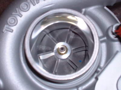 |
| Compressor Wheel |
Left to it's own devices the turbo will produce far more boost than the engine can cope with, so something has to be done to limit this boost before the engine expires:
When the valve is closed - all of the exhaust gas flows through the turbine spinning the wheel as fast as possible.
When the valve is open - some of the exhaust gas bypasses the turbine reducing the speed of the turbine wheel and directly reducing boost pressure
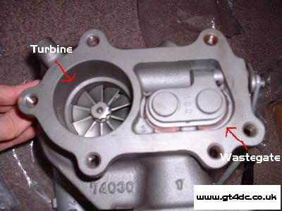 |
| Turbine and Wastegate |
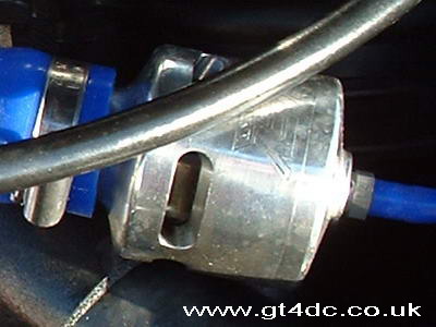
Actuators
The actuator is essentially a boost controlled switch. It is basically a diaphragm attached to a control arm which is directly connected to the wastegate. One side of the diaphragm is exposed to the boost pressure in the inlet manifold. Once boost pressure exceeds a certain base level (known as actuator pressure) the diaphragm will start to deflect. This will cause the control rod to start opening the wastegate, lowering boost pressure. It is a self regulating system. The more boost the turbo created the more the actuator will open the wastegate reducing boost
This state is actuator controlled boost and without changing the actuator the amount of boost pressure cannot be changed. Or can it?
Increasing Boost Pressure
In the GT4 system this is done with the VSV (Vacuum Solenoid Valve) system and it is done in different ways on different models...
In the ST165 and ST185 models the VSV is a simple system. It consists of (in simple terms) a fixed size nipple which will bleed off a set amount of pressure. This bleeding is controlled by a signal from the ECU. When the VSV is switched off the actuator is exposed to full manifold pressure. When the VSV is switched on a fixed amount of pressure is bled off (0.2 bar) which raises the intake pressure by 0.2 bar.
This is a crude but effective system. Variations in the actuator base pressure will result in identical variations in the inlet manifold pressure. The ECU cannot control this since it can only bleed off a fixed amount of pressure. So as the cars get older and the wastegates begin to loose stiffness the boost start to drop.
The ST205 model uses a different system. It has a VSV which is capable of bleeding off much more pressure (tests seem to show that it can bleed 0.5+ bar). If the VSV is permanently enabled then most ST205s will exceed 1.3 bar of boost. However, the ECU does not just switch the VSV on or off like the earlier models. Instead it uses a closed loop system to switch the VSV on or off based on boost pressure. The VSV is basically driven by a pulsed signal so that it is on some of the time and off some of the time. On average this switching will lower the amount of boost pressure which is bled from the actuator. So the ECU monitors the inlet manifold pressure and varies the on/off switching time of the VSV to ensure that the correct manifold pressure is maintained. This system is also (within reason) un-effected by degradation of actuator base pressure
Aftermarket Electronic Boost control
The boost controller rapidly switches the solenoid on and off (open and closed) exposing the wastegate to some of the boost pressure but not all of it all the time. By altering the ratio of solenoid open time to solenoid closed time (the duty cycle) the average pressure that the wastegate can be controlled.
In most aftermarket boost controllers the operator can either manually set a duty cycle or set a target boost and let the EBC control the duty cycle.
 |
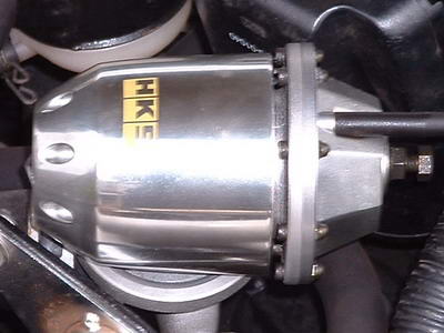
| Apexi AVC-R Boost Controller |
Dump Valves (Blow Off Valves)
One way of overcoming this is a dump valve. It connects to the inlet system after the turbo and allows the turbo to vent excess pressure
It works like this :-
The Dump Valve has a diaphragm (or a piston in an aftermarket setup) with a chamber either side. The "top" chamber is attached to the inlet manifold and the "bottom: chamber is attached to the inlet system before the throttle body. When the engine is turned off both sides of the diaphragm are at the same pressure and the elasticity of the diaphragm holds a piston arrangement shut preventing airflow through the mechanism. This is also true when the engine is on boost. With the throttle body butterfly open the exact same pressure is applied to the diaphragm. However, if you suddenly close the throttle butterfly (as during a gear change) the turbo is producing boost but the inlet side is in vacuum as air cannot pass the butterfly. This creates a pressure imbalance in the dump valve. The "top" chamber is in vacuum while the bottom is under pressure. This lifts the plunger mechanism off of its seat and allows air to flow through the valve back into the air box.
 |
 |
| Bailey Dump valve | HKS Super Sequential Dump Valve |
The ST205 is the only model that has a dump valve as standard and fitting one to other models can cause running problems unless it is done correctly. On these models the dumped air needs to be re-circulated back into the inlet system after the airflow meter but before the turbo.
Intercoolers
In order to combat this the output from the turbo is fed through an intercooler. This basically passes the hot air through a radiator where some of the excess heat is removed from it, cooling the inlet charge fed to the engine and allowing for maximum power.
Intercoolers come in two basic varieties and a whole host of different variations on these themes
Air To Water Intercoolers
 |
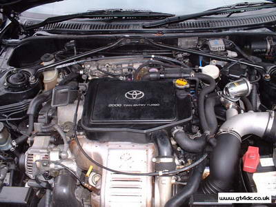 |
| ST165 | ST205 |
Chargecoolers use a water circuit to cool the air which comes out of the turbo. Essentially this air passes through a large sealed box (which can clearly be seen on top of the engines). Inside this box there is a large finned radiator which the hot air passes across. Running through this radiator is fluid which is heated as the hot air passes over it cooling down the air (or charge as it's known). To combat the heating of the fluid another radiator is fitted to the front of the car. Fluid from the chargecooler is circulated through this additional radiator to keep it cool. Overall the cool water removes heat from the compressed air and then the second radiator removes heat from this water
The major advantage of this system is that it keeps the path from the turbo outlet to the inlet manifold very short. This means that the dreaded turbo lag is kept to a minimum.
This system is fine but it does have limits. First of all there are two in-efficient exchanges of heat. One from the hot compressed air to the water cooling system and a second from the heated cooling water to the air outside the car. Secondly, sitting on top of the engine the cooler is also prone to heat soak when stationary for long periods. This is somewhat detrimental to overall performance
It is also worth noting that all of the stock systems are limited in their overall flow capacity. They were designed to work with a standard engine and while they will cope with increased boost pressure and flow there is a limit. Rumour has it the ST205 unit ceases to be effective somewhere close to 400HP so those aiming for figures above this should consider an upgrade.
Track testing has also shown that charge temperatures begin to climb alarmingly after 10-15 minutes of hard driving so those on a track biased mission should also seriously consider upgrading even with a standard engine
Air To Air Intercoolers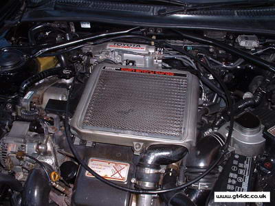 |
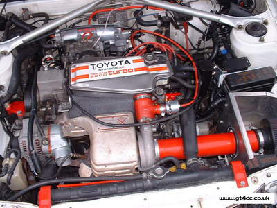
| ST185 |
This system is used on the ST185 as standard but in a flawed application. An air to air intercooler must have cold air flowing through it for it to be effective. Without airflow the hot turbo air will soon make it very hot and ineffective. In the ST185 setup the air to air cooler has two problems
First of all it uses a quite small bonnet vent to duct air over the IC core. This means that the flow of cold air is sub optimal and the core heats up more than it should do. Secondly the IC core is located on top of a very hot engine. This means that when airflow is slow (i.e. car not moving very fast or even worse stationary) the IC core rapidly reaches engine temps offering little to no cooling of the inlet charge.
The more optimal air to air system is the front mount setup commonly known as a FMIC. In this system the IC core sits right behind the front bumper. It is also generally considerably larger than the stock ST185 ATA core. This means that it has a high flow capacity and a much higher cooling capacity than any of the stock systems, be it air to air or water to air. Also, since the IC core is well away from the engine heat it does not suffer the heat soak problems which afflict all of the stock GT-Four setups. There are only two real disadvantages. Firstly the pipe runs are longer which can cause some additional turbo lag. Secondly the actual routing of the front mount pipe work is awkward since the stock car is not set up for a front mount system